|
JDM Power Folding Mirror
Conversion
Aspec and JDM triangle mirror mounts have different angles.
Because a different angle is needed when sitting in a RHD driver
seat, the angle of the triangle mirror mounts are different between
USA and JDM cars. Although there is limited viewing adjustment once
using JDM triangle mirror mounts, there is still enough adjustment
to allow using the JDM mirrors. There also seems to be a bit more
room for adjustment of the driver side mirror than the passenger
side mirror. I would consider the passenger side mirror to be on the
very edge of usable viewing angle and not able to be adjusted for a
maximum comfortable viewing angle.
In this writeup I will explain my attempts to combine parts from
both Aspec and JDM mirrors in an attempt to use the Aspec triangle
mirror mounts and why it can not be done. I will explain how to use
the heated mirrors since there will be no heated mirror switch after
the complete conversion. I will show the internal differences in
JDM, Turbo and Non-Turbo mirror switches as well as a complete
breakdown of the switch themselfs. I will explain how to de-pin the
connectors which go to the switch and how to easily move the pins
from the USA to the JDM switch connector. I will show how you can
use your original Aspec mirror housings so no need to worry about
painting (you must use your Aspec mirror glass). I will also show
how you can not use a JDM mirror glass with an Aspec mirror housing.
The JDM mirrors I purchased only had a heated RH driver side
mirror. The JDM left side mirror was not a heated mirror. I do not
know if this is an option in Japan or if all JDM heated mirror sets
are like this. If the JDM mirrors you have do not have a heated left
side mirror, this writeup will help you in converting your left side
JDM non-heated mirror to a heated mirror.
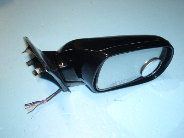
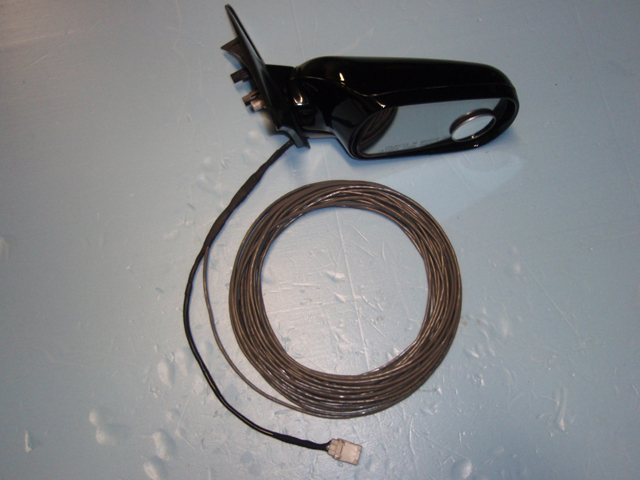
JDM Mirror
Disassembly
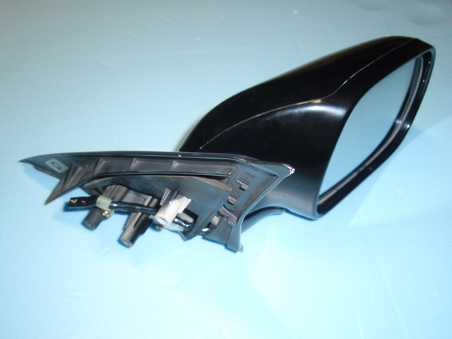
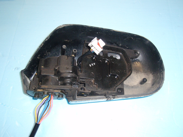
Rightside JDM mirror.
Rightside JDM triangle interior view. Remove these
two pieces.
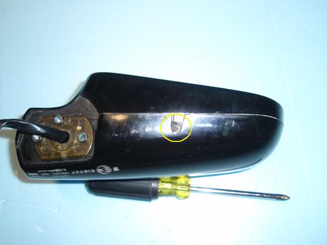
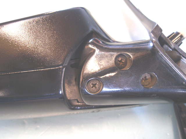
Rightside JDM mirror bottom.
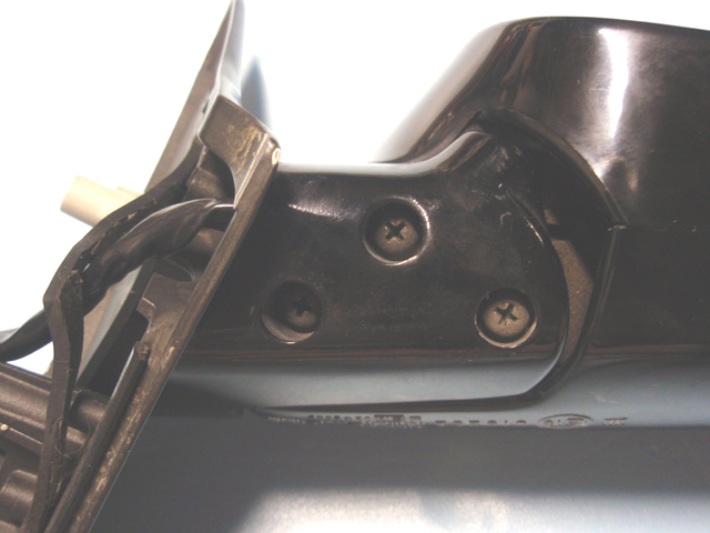
Rightside JDM mirror seperated from the triangle
mount by removing three screws.
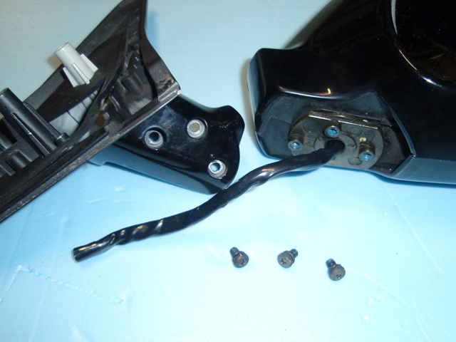
Removing this screw frees the glass mirror from the
housing.
Once you free the glass, disconnect the white
connector to the mirror angle motor by pressing the tab while
pulling.
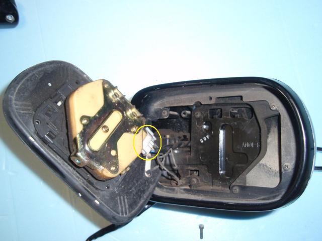
The connector unplugged.
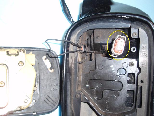
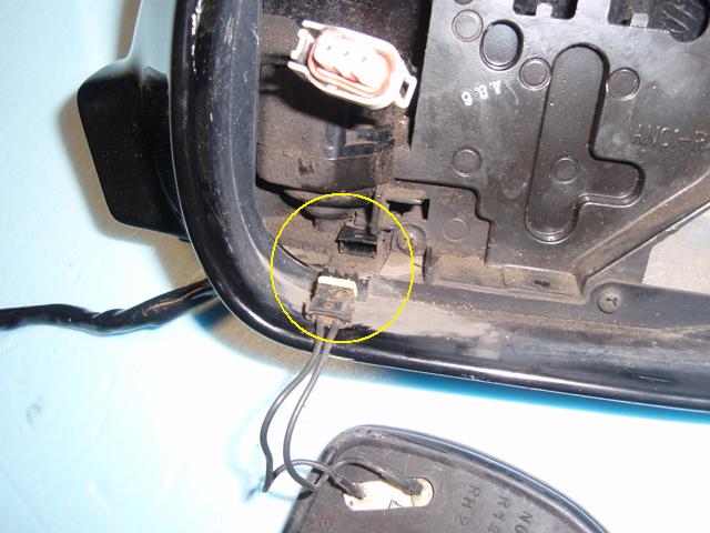
Disconnect the heated mirror connector using a small
flat-tip screwdriver. Pry up on the flat piece which is holding the
connector in place while pulling on the connector wire.
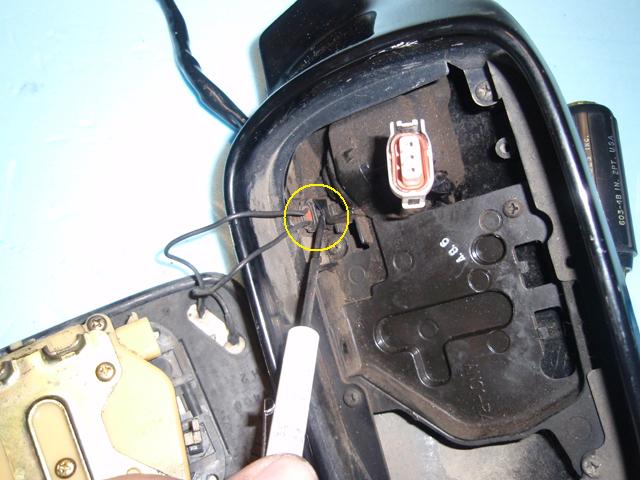
The heated mirror disconnected.
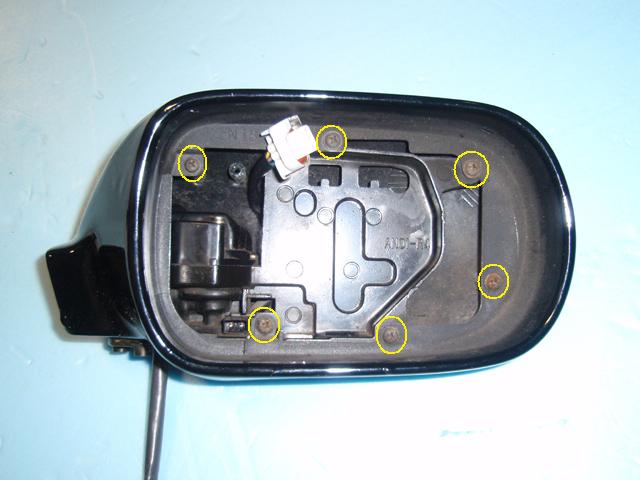
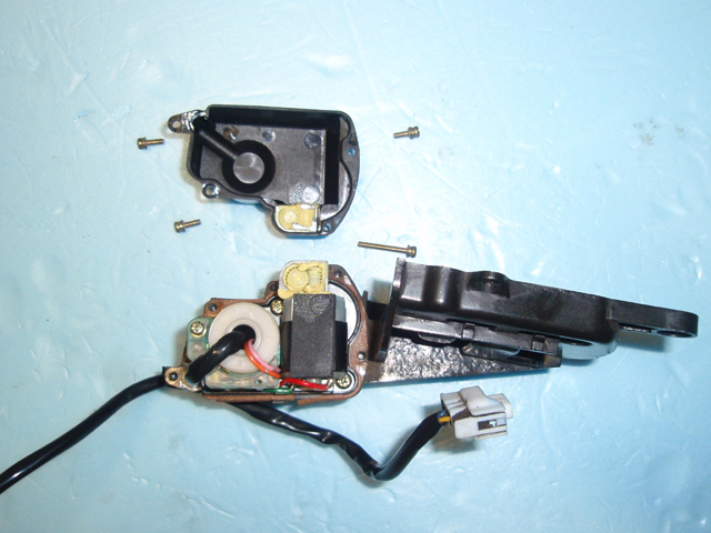
Once the mirror glass has been removed, seperate the
two halves of the mirror housing by removing these six screws.
Remove these two screws to remove the internal
piece.
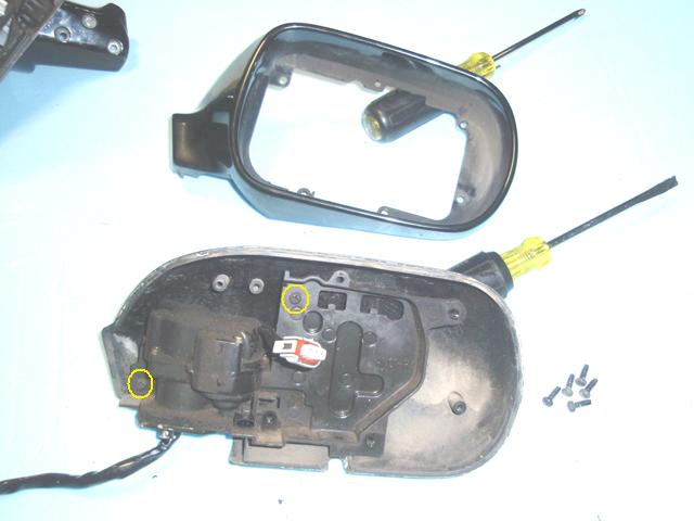
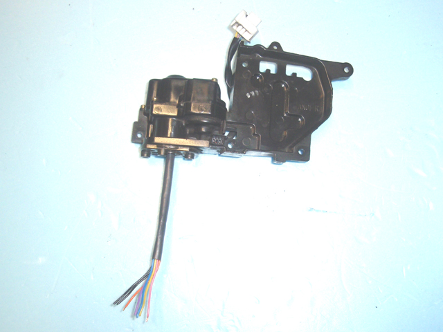
The JDM internal piece removed.
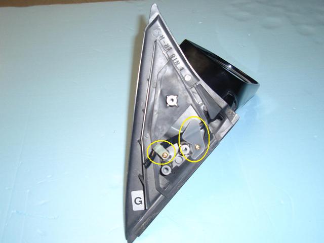
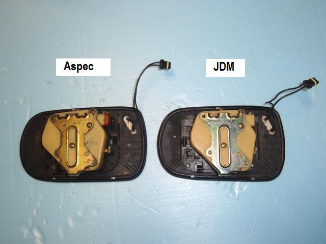
Here is a picture of the difference between the Aspec
and JDM internal pieces. The JDM internal piece is a part of the
lower half of the folding motor housing in one complete molded
assembly. You can also see that the piece with the three holes which
is used to bolt the mirror to the triangle mount (circled in yellow)
are slightly different. This piece is a part of a metal tube shaft
which extends up through the center of the folding motor in the JDM
mirror. It is used as a tunnel for the mirror harness and heated
mirror wires. The holes of this piece do not line up with the Aspec
triangle mount. Even if the holes were to line up it would raise the
mirror up and produce a gap.
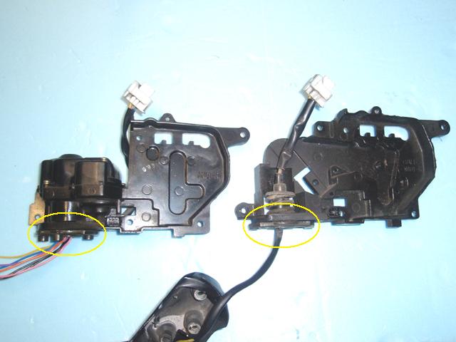
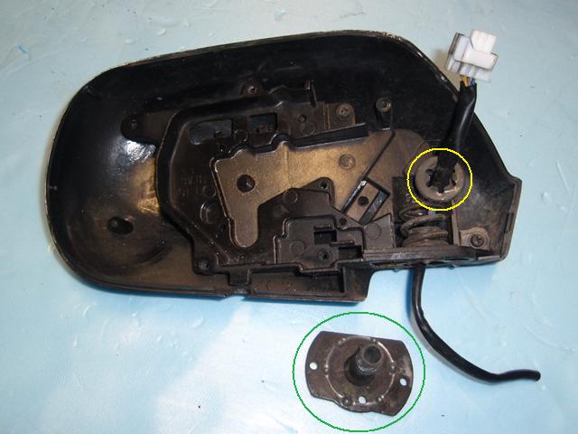
I thought it might be possible to swap this mounting
collar and shaft (circled in green) with the one in the JDM mirror
to allow mounting the JDM mirror with folding motor to the Aspec
triangle mounts. If it was possible, it would allow normal viewing
angle for our US cars. The piece is held in with a locking ring
circled in yellow.
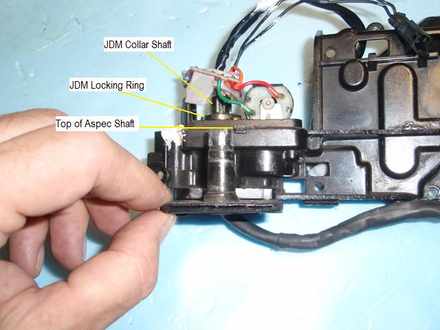
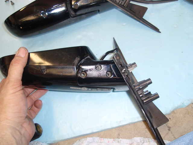
Holding the mounting collar in front of the partially
disassembled JDM folding mirror motor you can see that the shaft of
the Aspec piece is much shorter than the one in the JDM mirror. This
will not allow it to be used due to the length needed for the
locking ring that holds it in place.
=============================================================================
Installing Heated Mirror Wire
and Connector
I have heard that all JDM heated mirrors do not have
a heated passenger side mirror (our driver side mirror). This part
of the writeup will explain how to turn our driver side mirror into
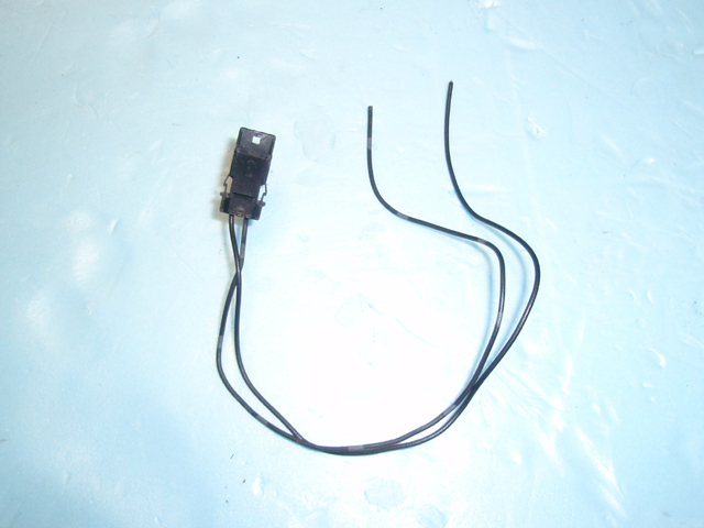
a heated mirror. First, remove the heated mirror wire and connector
from either the driver side or passenger side of the Aspec mirror as
located below (they are both the same).
Using a small screwdriver, push in the locking tabs
on both sides of the connector and pull the connector through the
hole toward the wire side.

Below is a picture of the connector and wire
removed.
Remove the folding motor cover by removing four
screws from the top of the motor cover.
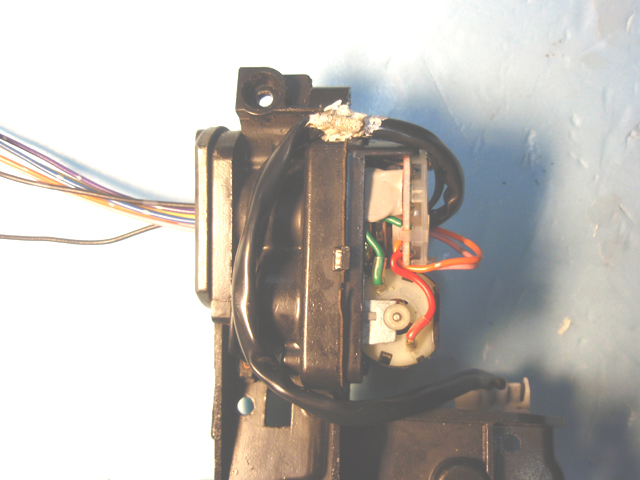
Below is a picture of the folding motor before the
heated wire connector is installed.
Insert the connector's wires through the collar
shaft hole in the same way that the mirror control harness is
routed.
Route the heated mirror wires and install the heated
mirror connector into the available hole.
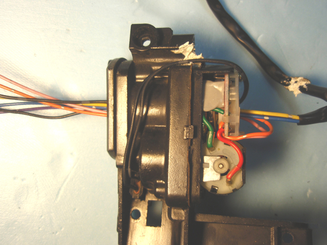
Route the mirror control harness as it was before.
The white substance is goop similar to the black goop that seals
door panel plastic and rear tail lights.
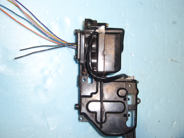
Reinstall the folding motor cover.
After completion, reassemble the mirror housing in
the reverse order as the disassembly. Once you have done that,
reattach the assembled mirror housing to the triangle mount and feed
the harness through the triangle mount as it was before.
=============================================================================
Color Code and Harness
Install
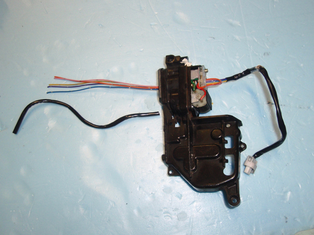
Using the picture below, here is the color code for
the JDM mirror wiring. Both JDM and Aspec left and right mirrors
uses the same color code.
Mirror angle motor = Yellow, Violet, Blue
Heated mirror = Black, Black
Folding Motor = Orange, Pink
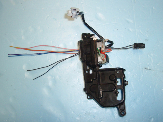
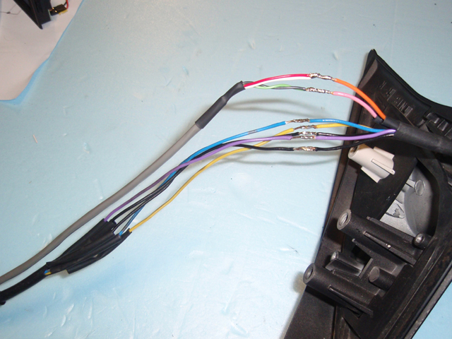
The only thing needed is to add a wiring harness to
the wires which control the folding motor. My JDM mirrors only had a
few inches of harness and no connector. Because of this I used the
harness from my Aspec mirrors and spliced them to the JDM harnesses.
I also added a seperate harness for the two wires that controlled
the folding motor. As you can see in this picture I soldered pairs
of wires to each folding motor wire. I did this to allow a branch to
my alarm system which will automatically fold the mirrors when I
remote lock my car. I'm sure this could be done a different way
though. You will need to route this additional harness through the
door, into the car's cabin and to the mirror switch. You can not use
the heated mirror wires. They are not routed directly to the mirror
switch.
Heatshink covering the splices.
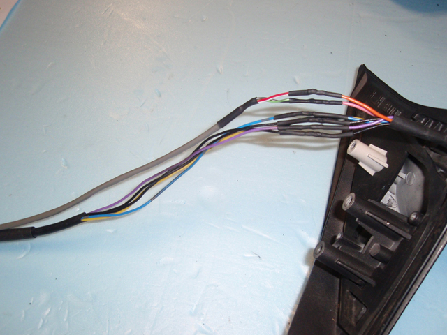
Heatshink covering all the harness splices.
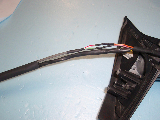
Heatshrink covering both harnesses and the completed
mirror ready to install.
=============================================================================
Comparisons
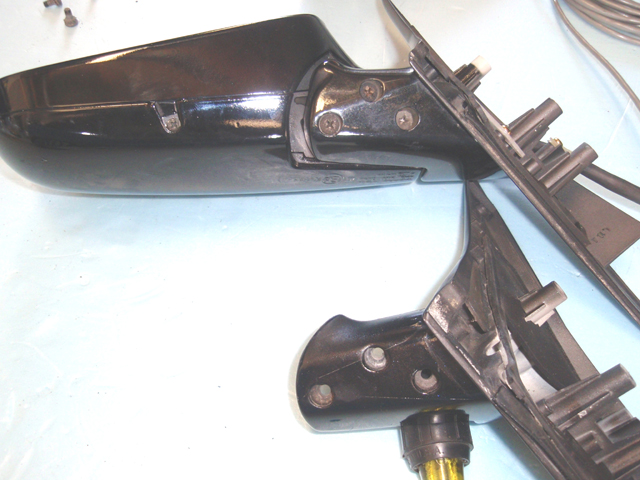
This is a bottom view of the Aspec mirror housing
containing the JDM motor assembly attached to the JDM triangle. As
you can see, due to the shape of the bottom of the Aspec housings to
match the angle of the Aspec triangle mounts, using them with the
JDM triangle mounts allows plenty of gap between the housing and
mount to allow the mirror to fold.
You must use your Aspec mirror glass when using the
Aspec mirror housings. This is because of the position of the hole
for securing the mirror glass. As you can see in the picture below,
the metal part of the JDM mirror glass is slightly shifted to one
side as compared to the Aspec mirror of the same side. If you buy a
JDM mirror for the mirror glass you will not be able to use it with
your Aspec mirror housing.
This is a picture of JDM housings containing the Aspec
internal piece being held up to an Aspec triangle. As you can see,
aligning the first screw hole (left) shows how there is not enough
clearance for the mirror to pivot or even attach to the triangle
mount due to the obstruction from the shape of the JDM housings. So
if you buy a set of JDM mirrors because you want the housings for
your Aspec mirrors, forget it, they will not work. You can use Aspec
housings with the complete JDM mirror assembly but you can not use
JDM mirror housings with the complete Aspec assembly. This is good
though! You do not have to repaint mirror housings when you do the
conversion. Just use your original ones.
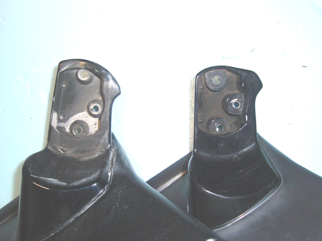
In the top of this picture is the JDM driver side
assembly with aspec mirror housings. At bottom is the driver side
triangle mirror mount. As you can see, there is a difference in the
shape of the area of the mount on the left side near the first screw
hole (left). You can also see how there is a larger distance between
the center and right screw holes. So basically, even with the mirror
housings completely removed you can not mount an Aspec mirror
assembly to a JDM triangle mount and you can not mount a JDM mirrow
assembly to an Aspec triangle mount because all three holes will not
line up.
Another picture showing the difference between the
Aspec and JDM mirror mounting holes on mirrors of the same side.
=============================================================================
Converting the Mirror
Switch
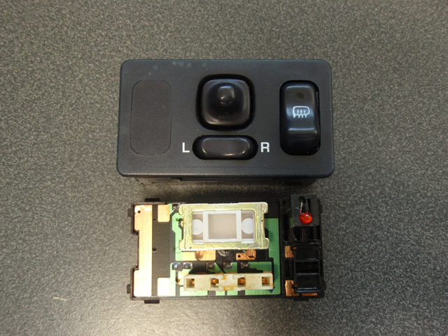
Here I will show the differences between three mirror
control switches. I will show each switch from assembled to
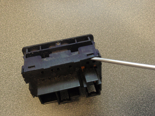
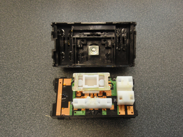
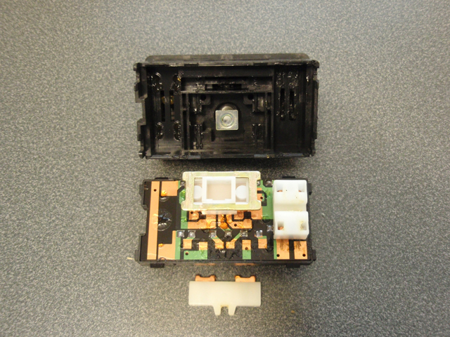
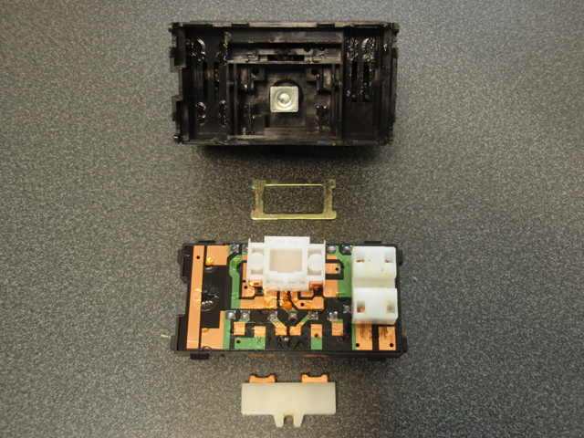
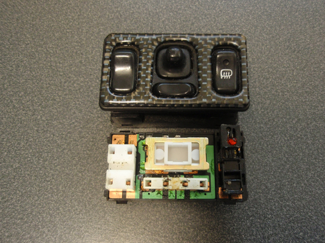
disassembled in step by step breakdown. But first, here is how to
disassemble the two main parts of the switch.
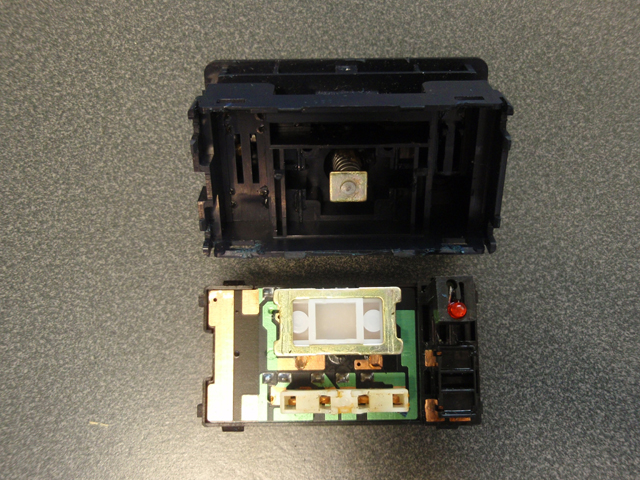
Using a small screwdriver, place it between the
plastic in each locking tab location to pry the housing apart.
=============================================================================
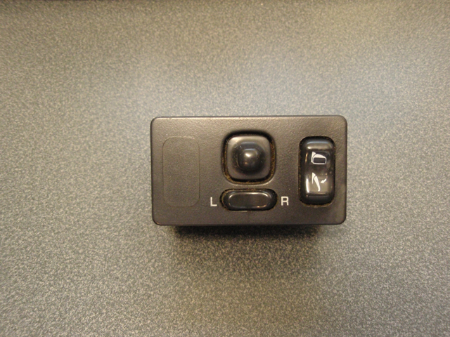
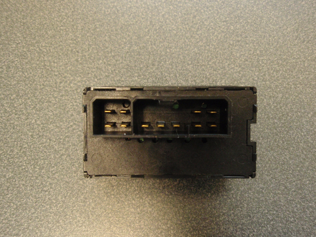
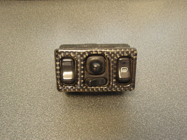
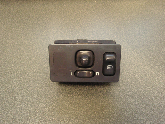
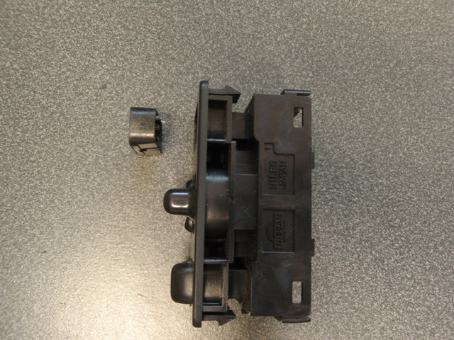
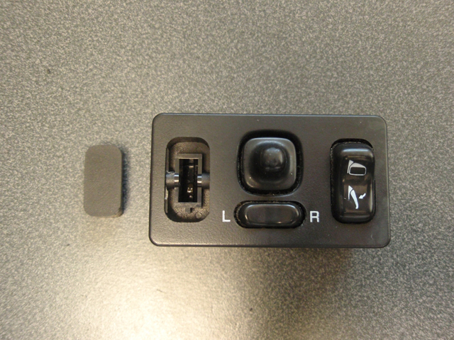
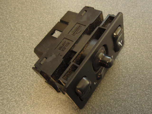
JDM
Switch
Folding Mirrors and Mirror Control
=============================================================================
USA Twin Turbo
Switch
Defogger, Mirror Control and Adjustable Shocks

=============================================================================
USA NA
Switch
Defogger and Mirror Control
=============================================================================
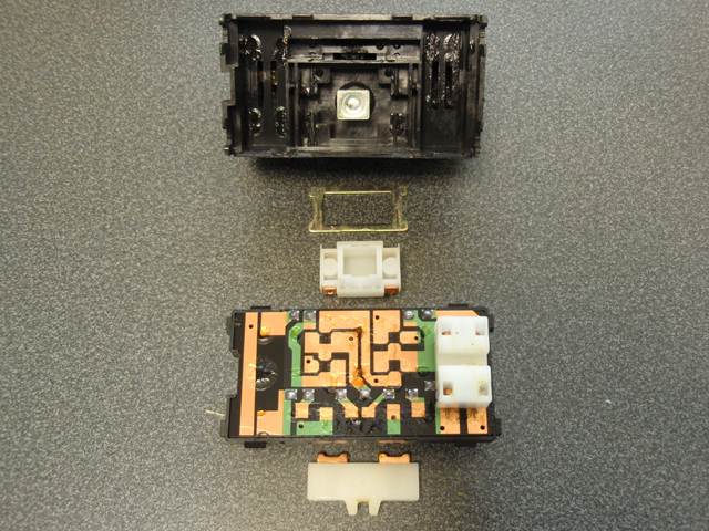
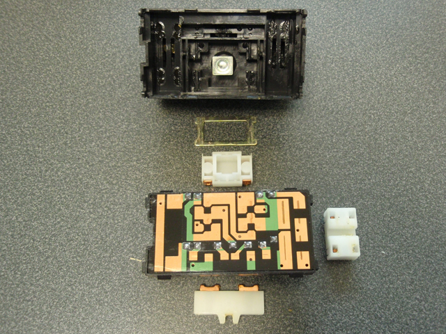
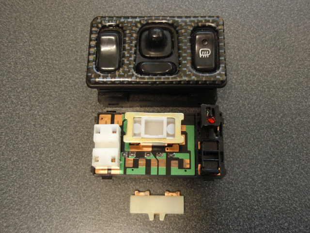
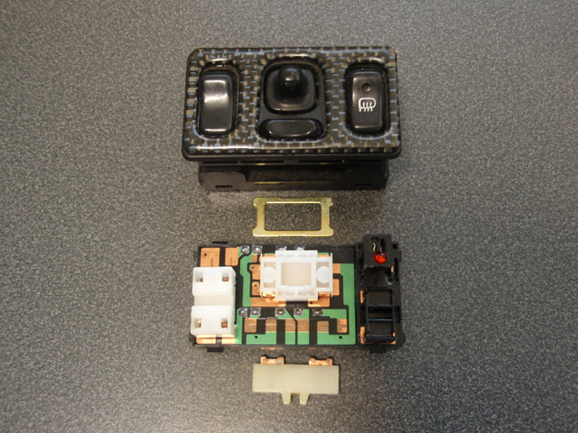
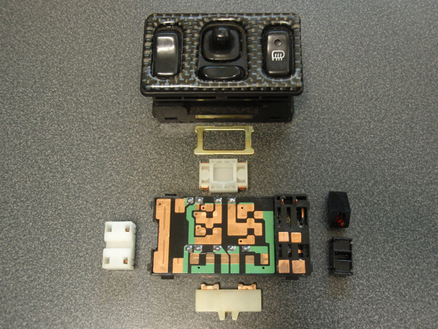
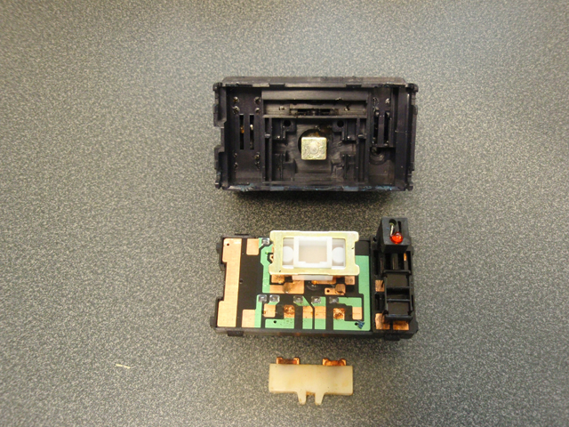
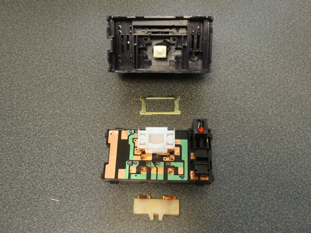
Internal
Comparisons
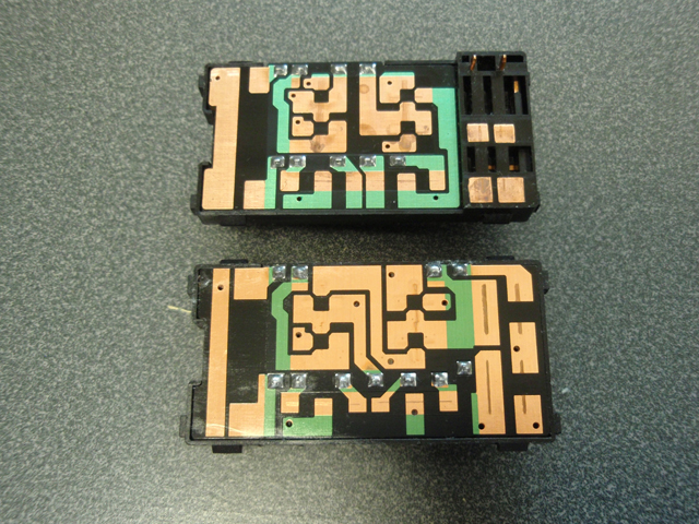
USA on top and JDM on bottom.
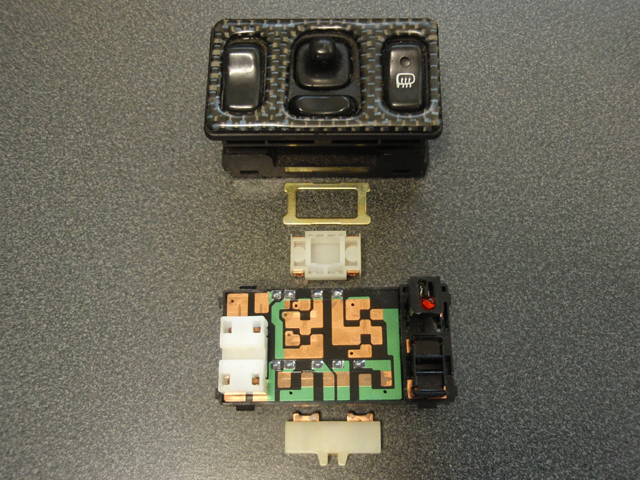
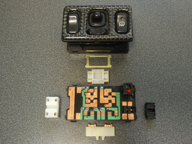
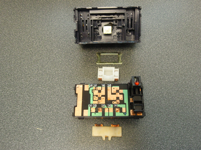
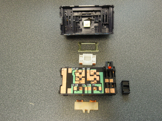
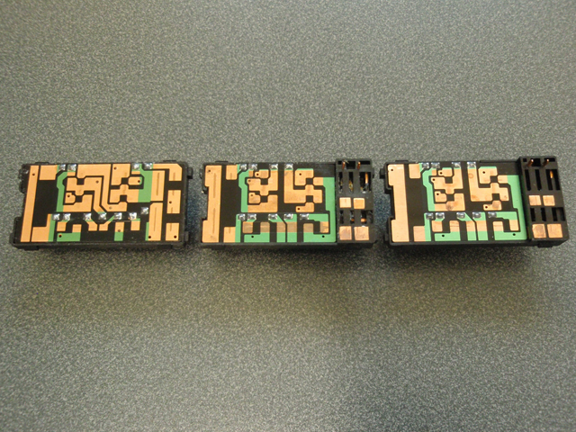
From left to right. JDM, USA Twin Turbo and USA
Non-Turbo. USA Twin Turbo and USA Non-Turbo are physically the
same.
=============================================================================
Selector Switch Pin and
Selector Removal
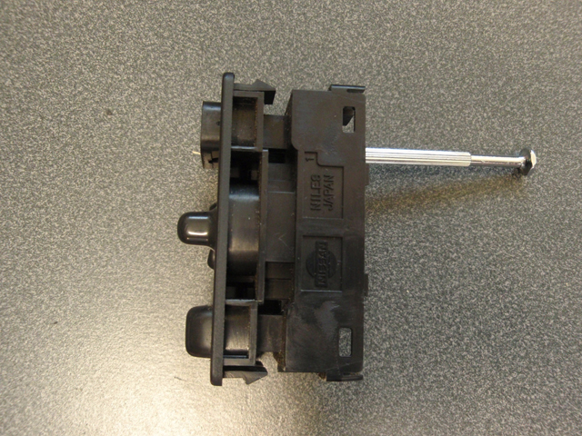
You must use the JDM switch assembly for the switch
conversion. You must also remove the adjustable shock selector from
the twin turbo switch assembly and install it into the JDM switch
assembly unless your JDM switch already came with an adjustable
shock selector switch.
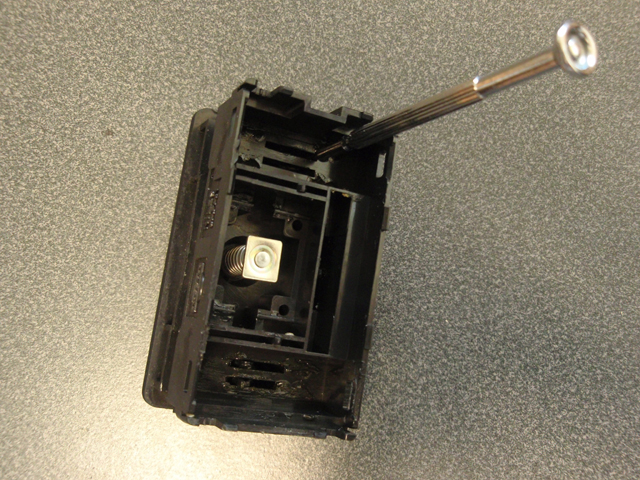
Remove the pin that holds the adjustable shock
selector switch. In this picture the pin is partially out.
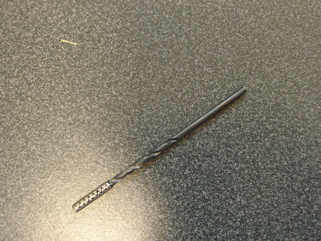
I found it easy to use a .082 size drill bit to
remove the pin. It is slightly smaller than the pin's hole. Pull out
the pin while bending the drill bit at a slight angle and rotating
the drill bit. The cutting surface of the drill bit grabs the pin
very well.
Shock selector switch removed.
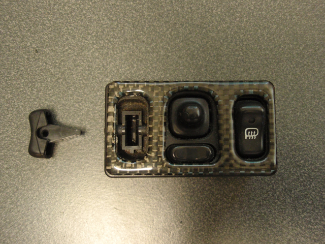
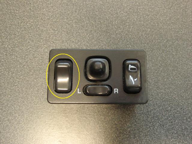
If you have a JDM mirror switch with a blank
selector switch in the adjustable shock switch position such as I
did, remove the pin which holds it in the same way you removed the
adjustable shock selector switch pin. Once the pin is removed, use a
jewelers screwdriver of appropriate size and push it through one of
the long slotted holes to push out the blank selector switch.
=============================================================================
Assembly of Converted Mirror
Switch
Install the adsjustable shock selector switch into
the JDM mirror switch where the blank switch was located. Normally
there is a picture of a shock on the shock selector switch. Mine has
worn off.
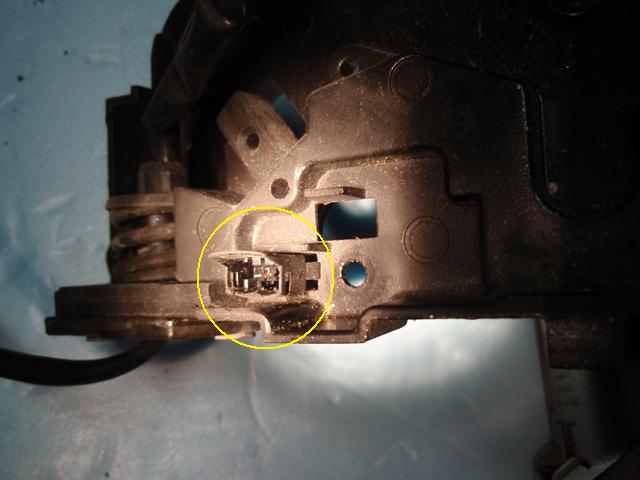
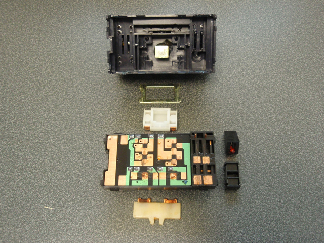
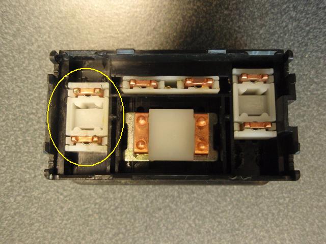
Once the shock selector switch is installed, turn
the complete switch assembly over and install the internal
components as pictured below. You will need one component from the
USA Twin Turbo switch (circled in yellow). This piece will be under
the shock selector switch to allow it to function.
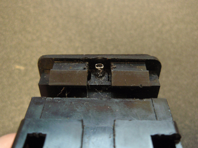
Snap the JDM circuit board half of the switch
assembly in to place by flipping this piece over onto the half as
pictured above.
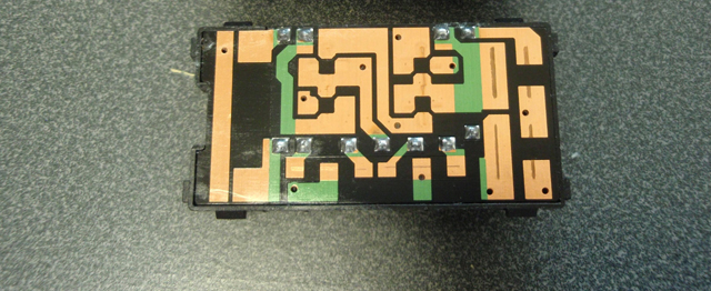
Completed and ready to install.
==============================================================================
How to De-Pin the Switch
Connector
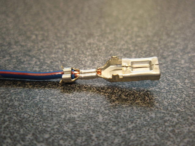
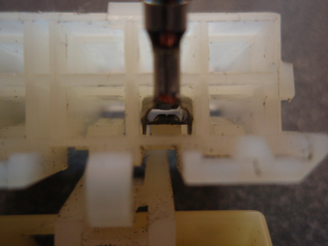
Here is a picture of a pin removed from the
connector. This is the side which the plastic catch in the connector
will grab keeping the pin from comming out.
Here is a picture of how the pin is inserted into
the back of the connector.
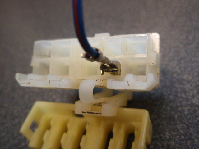
This is a picture of the pin in the tunnel before it
is pushed over the spring catch.
In this picture the pin on the left has been pushed
into the tunnel over the spring catch which locks it into place. The
pin on the right is shown just before it is to go over the spring
catch. To remove the pins, use a jewelers screwdriver of appropriate
size and insert it into the pin tunnel to press down on the spring
catch to release the pin. You will need to pull on the pin's wire at
the same time you are pressing on the catch.
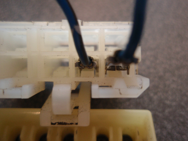
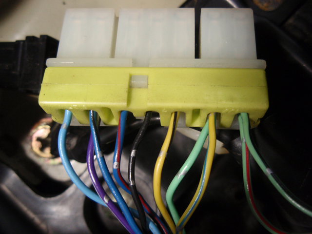
Here is a picture of the stock USA pins in the JDM
connector. The two wires at the top of the connector (green w/red
stripe and green w/black stripe) are original JDM wires to be used
for the power folding mirror motors (see diagram below).
Another picture showing the two original JDM wires
to be used for the power folding mirror motors.
Here is the connector once the wire guide/pin cover
is put back into place.
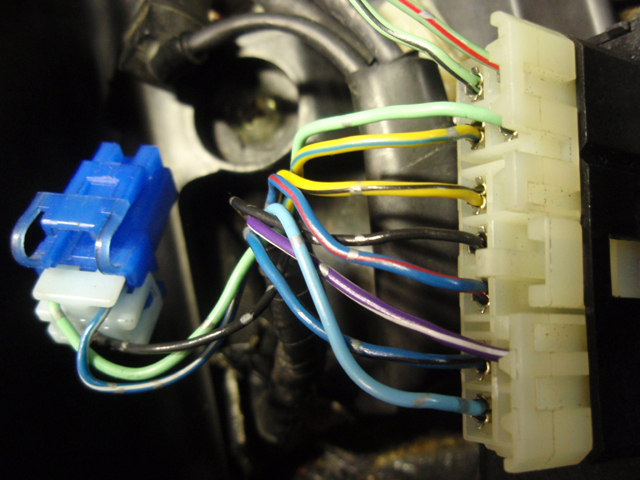
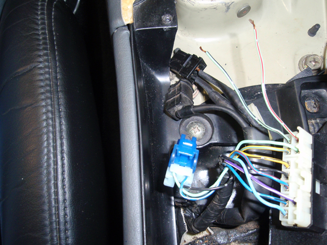
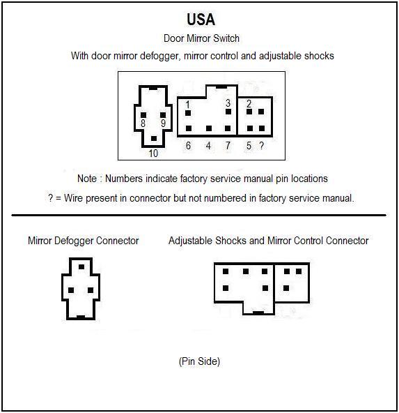
The diagram I have made below explains the use of
the USA Door Mirror Switch connectors which attach to the Door
Mirror Switch.
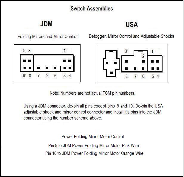
The next diagram I have made below explains how to
move the wires from the USA connector to the JDM connector. The
connector for the mirror defogging control is not used for this
conversion but I will explain how to use those wires in case you
would like to have heated mirror capability. The diagram also
explains which wires are to be used for the power folding mirror
motor control.
==========================================================================
Heated mirror
operation.
For heated mirror operation, connect pin 8 of the
Mirror Defogger Connector to switched 12vdc at either ignition ACC
or ignition ON. Then, to turn the heated mirrors on, connect pins 8
and 9. Pin 10 of the Mirror Defogger Connector is normally connected
to ground and is only used to operate the LED ON light in the
original heated mirror switch.
==========================================================================
Finished
Thank you for reading this long writeup. I have
completed my installation of the JDM power folding mirrors and they
are working very well. I had been wanting to do this for a long time
and now that it's done it feels great. With this information you
should have no trouble installing your own JDM power folding
mirrors. Have fun, good luck and enjoy!
(Total Mouse Over Hits: a Lot)
http://www.twinturbo.net/nissan/300zx/forums/technical/view/1066651/www.mytwinturbo.com
Watch an
ECZA meet caravan!
|


 JDM Power Folding
Mirror Conversion. (Long!) -
JDM Power Folding
Mirror Conversion. (Long!) -