| I know there has already been a couple of
write ups on killing the constant injector voltage. Here is a little
info on how you can kill the power to the injectors and at the same
time give you the ability to keep someone from starting your car by
adding a kill switch.
This should probably be in the tech forum but there is also
something different in the after photos of the fuseable link box
that is different than in the before pics. I though it would be fun
to see if anyone can guess what it is.
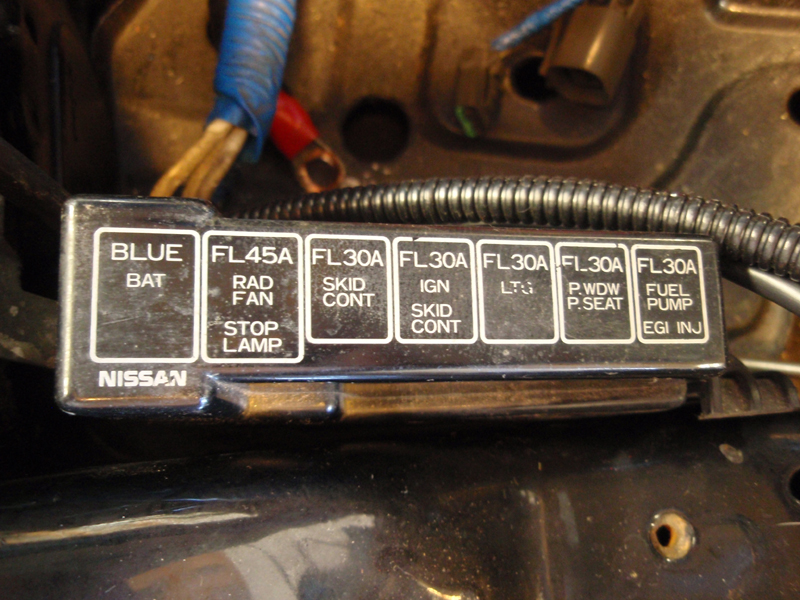
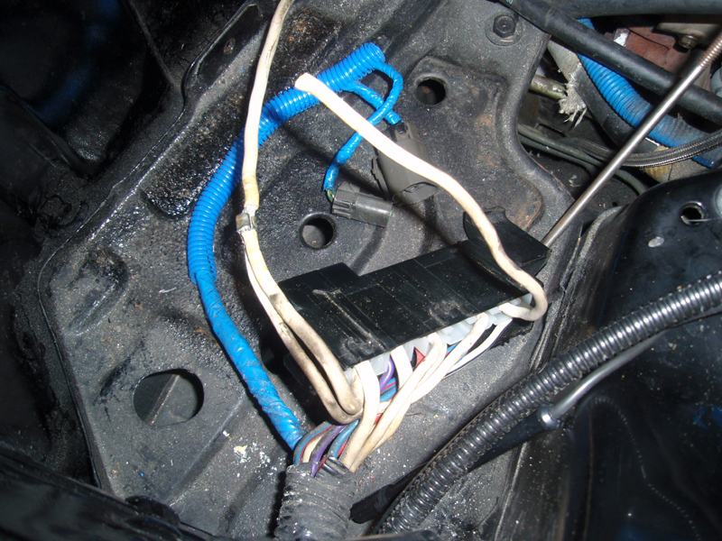
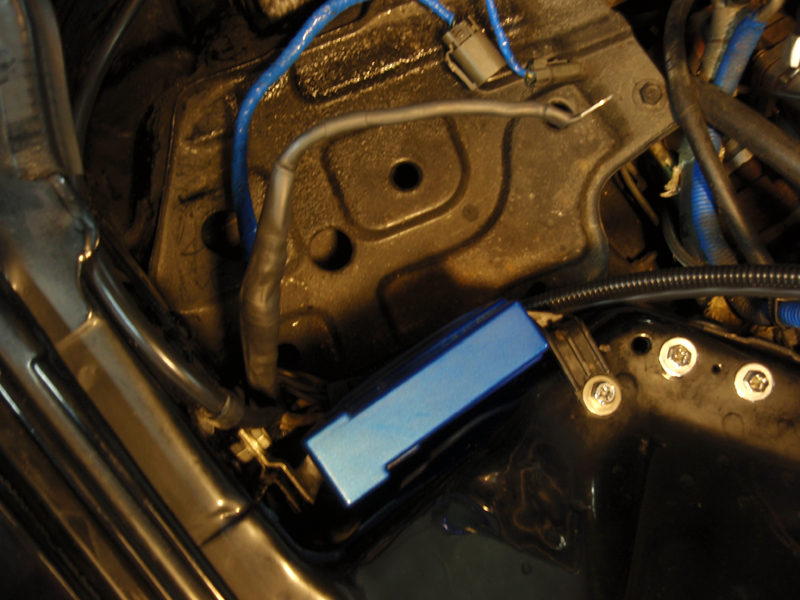
Getting started, here is the fuseable link box. All the way to
the right is the fuse for the fuel pump, ignition coils and the
injector voltage. The injector voltage is the voltage which is
always applied to the injectors in the 90-94 Zs.
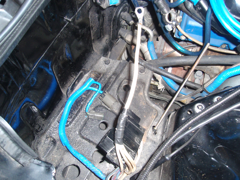
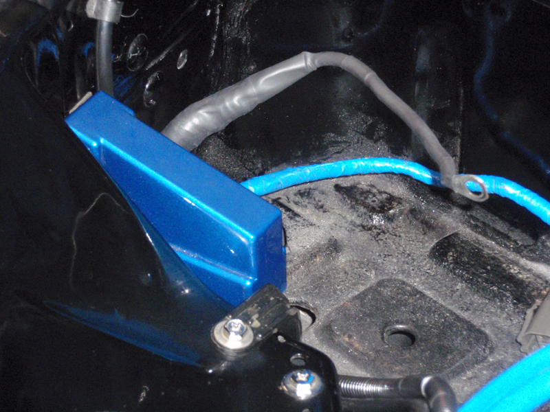
Here is the single smaller wire which goes to the positive
terminal of the battery along side the battery's larger main
positive cable. This wire has been known to break at or near the
terminal and cause the Z to not start. In this picture most of the
wrapping has been removed to expose the wire. You can also see where
it forms into three wires as it gets close to the fuse box. The
Nissan factory electrical tape is still on at the splice.
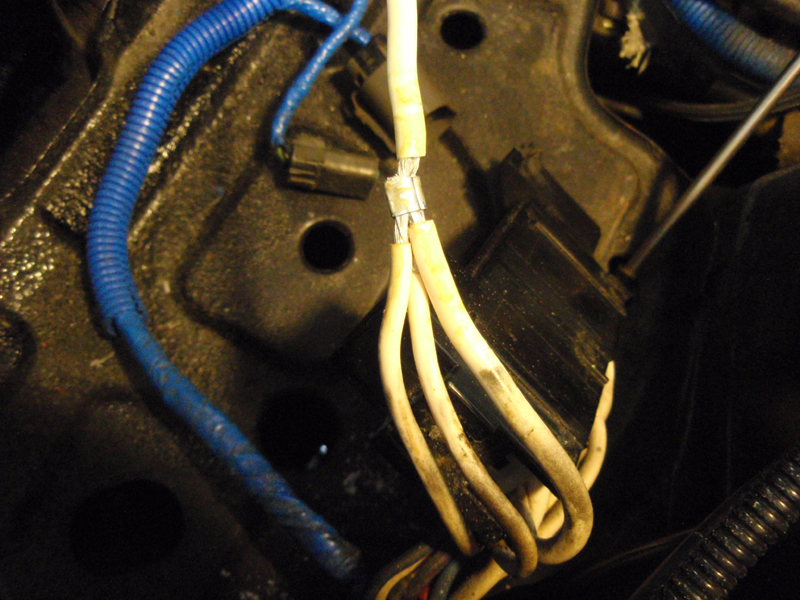
Here is the wire again but this time with the splice
exposed.
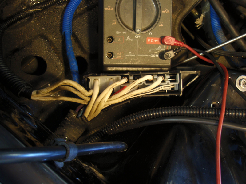
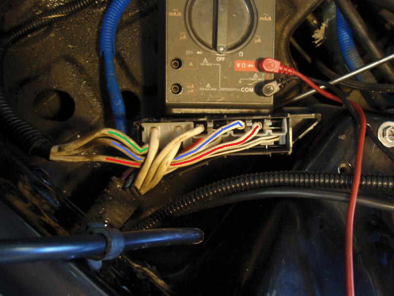
Here is a picture of the fuse box flipped over and with the
bottom cover removed to show where the three white wires go.
Below is the same picture except this time I have added a green,
blue and red stripe to the wires so you can see more clearly which
wires they are and where they go. Using the picture of the fuse box
cover as a reference, the wire with the green stripe goes to a
single gang terminal to the "BLUE BAT" fuse which goes to the
alternator.
The wire with the blue stripe goes to a single gang terminal
which provides constant power to the "LTG" fuse. The wire with the
red stripe goes to a two gang terminal and provides power to two
fuses. They are the "P.WDW/P.SEAT" and "FUEL PUMP/EGI/INJ" fuse.
This is the wire we want to use for our voltage control to the
injectors and the kill switch.
Here is the wire cut away from the three way splice. All that's
needed for a kill switch and to remove the voltage from the
injectors is to run two wires from a toggle switch and connect one
of them to the wire which was cut from the three way splice and the
other one to the splice where you cut the wire from. Instead of a
toggle switch you could use a relay and control it from a switched
power source. With this one wire disconnected there is no power to
the injectors, coil packs, fuel pump, power windows or the power
seat.
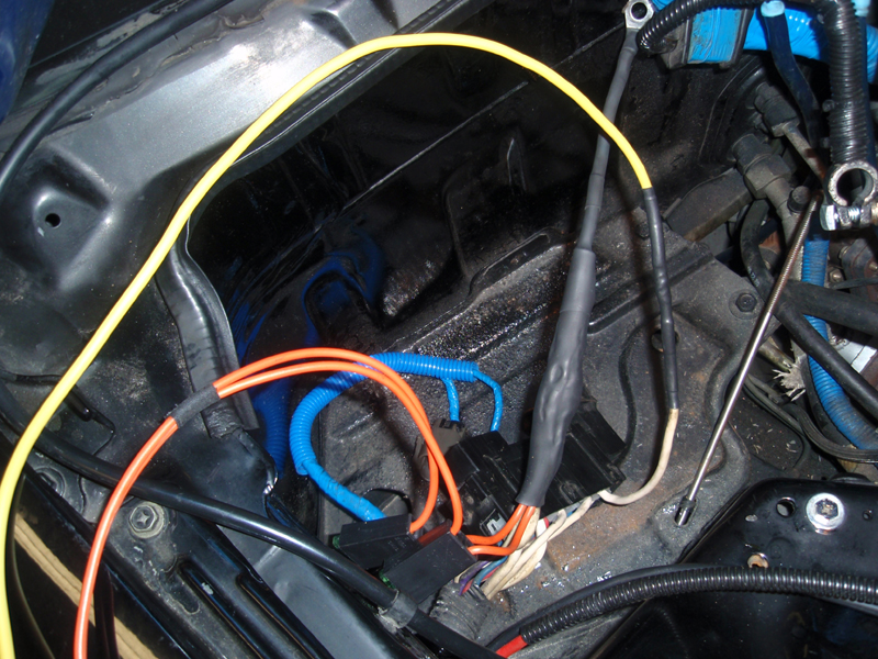
For my needs I ran two wires (orange) with in-line 30amp fuses to
the three way splice for two sources of constant battery voltage and
a wire (yellow) to the wire I cut away from the three way splice to
be used for a kill switch.
You must run the wires under the fuse box as they originally were
in order to put the bottom cover back on.
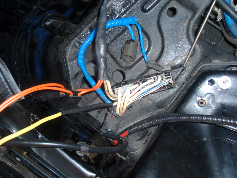
Everything back together with the wires and in-line fuses now
through the harness hole and inside the fender well where the wires
run to a hole which routes them to the cabin.
And one last picture of it completed. Now can anyone tell what is
different? There is one main thing I'm looking for.
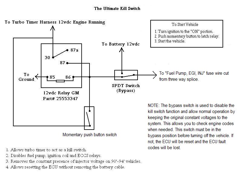
And lastly, here is a schematic with explaination of the kill
switch function and how to use it. The schematic shows how to use
the kill switch with a turbo timer. Once the turbo timer turns off
the vehicle the car can not be started until the relay is latched by
pressing the momentary push button. I'll place this post in the tech
section in case anyone would like to vote it to FAQ. Thanks for
reading!
(Total Mouse Over Hits: a Lot)
http://www.twinturbo.net/nissan/300zx/forums/general/view/2187308/www.mytwinturbo.com
|


 More info on
killing the constant power to the injectors. -
More info on
killing the constant power to the injectors. -